Help with WP374 Please

Trashman

Member
Installing the WP374 into a 2004 Chopper. Cover page on documentation from Wire Plus has a Rev date of Jan 19, 2011. Installation instructions are 8 pages plus a block diagram of wiring.

Step #9. Route the red wire form the power module to the SILVER (Aux) side of the 30 Amp breaker. Trim to length....I presume the original wiring that was on the 30A breaker still get connected? Black to Silver post & Red to Copper post on the breaker?

Step #31. Cut grey wire off of the 2004 EHC module. Plug into position 3 of plug #3.
At this point during the installation I have NO GREY wires left to cut on the EHC module!

Step #34. Using a butt splice from the kit, combine the following tach wires: a. Green wire, EHC position 20. & b. Yellow wire, EHC position 21.
At this point during the installation I have NO YELLOW wires remaining to be cut!

When cutting wire from EHC connector I used a magnifying glass and performed a continuity test from pin side of connector to the wire side of connector. What the hell am I missing hear??

I also received a bag with a triangular shaped Deutch connector (3-pin). Is this for the new key switch??

For those of you who have done the install. Did you solder the wires in the butt and spade connectors or did you crimp???

I have not been on the bike in about a year and am looking forward to getting her up and running. Any help would be appreciated.

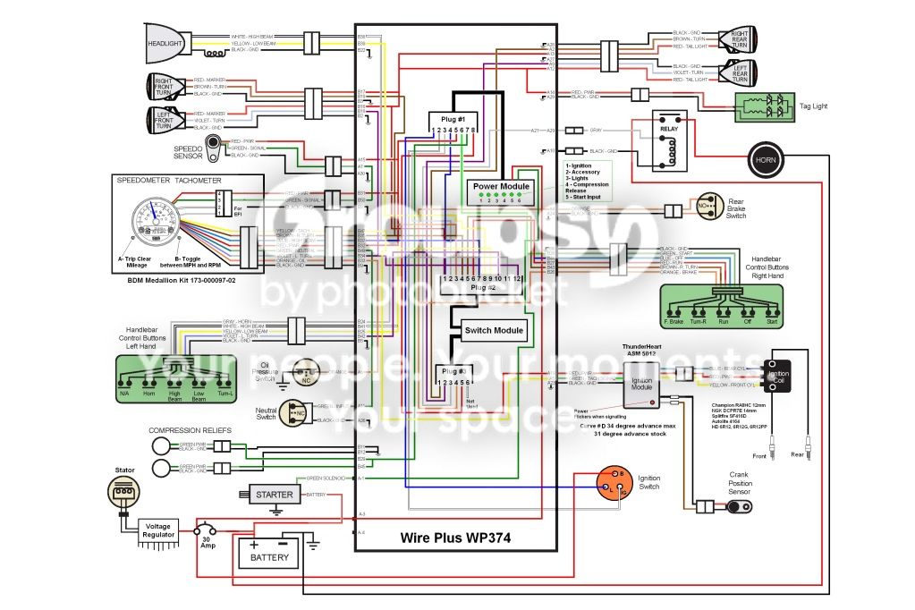
Also saw a post and requested a copy of a WP374 schematic one of the members came up with. Anyone have a copy they could send me?

Thanks
 

awg

Guru
I bought the "simple" kit from Jake. Here is what I did to my 04 RT.

Step #9 I took the red wire from the module and hooked it into a 20amp inline fuse holder and hooked that to the positive side of the battery. I did not touch the wires on the breaker.

Step 31. The gray wire is the horn. Find your horn then the wire. Follow it up to whereever it goes. It has to be there. You may of cut it sometime during The install. Thats why I say find the horn then the wire then follow it up.

Step 34. I had the yellow and the green in my install. The only thing I can think of is some how those wires got cut during the install? They have to be there.

I to used a magnified glass to make sure I cut the correct wires. I did notice that some of them would twist and end up in a different position on the connector. Thats why its so important to check and recheck what wires you are cutting.

I hope I was able to shed some light on your problem. I know how frustrating this can be. I must of been the lucky one doing mine. After I did mine my BD fired right up. Haven't had any problems yet. Well except for a wire that came out of the connector. I didn't crimp it good enough. Well if you need any help please send me a PM. I will try where I can to lend you a hand.
 
Last edited:

CURDOG

Active Member
I watched Jake do mine yesterday and it's very important to take the time to remove all the silicone from the EHC amphenols before you start to reduce confusion and mistakes in cutting the wires. Connectors should be crimped and take your time crimping and check the crimps as you go. Also, make sure you push the crimped barrels into the connector housings properly so they snap in securely. :up:
 

Th3InfamousI

Administrator
Staff member
Installing the WP374 into a 2004 Chopper. Cover page on documentation from Wire Plus has a Rev date of Jan 19, 2011. Installation instructions are 8 pages plus a block diagram of wiring.

Step #9. Route the red wire form the power module to the SILVER (Aux) side of the 30 Amp breaker. Trim to length....I presume the original wiring that was on the 30A breaker still get connected? Black to Silver post & Red to Copper post on the breaker?
Power module red wire to a inline 20A fuse straight to the battery is what you need to do here.
Step #31. Cut grey wire off of the 2004 EHC module. Plug into position 3 of plug #3.
At this point during the installation I have NO GREY wires left to cut on the EHC module!
As far as I can recall the Grey Horn wire is the only Grey wire on the entire bike. The grey wire was directly into EHC it was 1 out of 5 that was ran direct into the EHC and not through the pin connector.


Step #34. Using a butt splice from the kit, combine the following tach wires: a. Green wire, EHC position 20. & b. Yellow wire, EHC position 21.
At this point during the installation I have NO YELLOW wires remaining to be cut!
This is a problem - these wires are not used at all they actually just get spliced together and shrinkwrapped and tucked away. However I imagine that you got the Yellow 20 Wire stuck in some other hole. It's a pain to deal with if you stick it in some other hole :lol:

When cutting wire from EHC connector I used a magnifying glass and performed a continuity test from pin side of connector to the wire side of connector. What the hell am I missing hear??

I also received a bag with a triangular shaped Deutch connector (3-pin). Is this for the new key switch??
Correct, 3 pin is for the new key switch under the tank.


For those of you who have done the install. Did you solder the wires in the butt and spade connectors or did you crimp???
Soldered the wires for the butt connectors, crimped the pins that plug into the WP.
I have not been on the bike in about a year and am looking forward to getting her up and running. Any help would be appreciated.

Also saw a post and requested a copy of a WP374 schematic one of the members came up with. Anyone have a copy they could send me?

Thanks
 

bdmridgeback

Low Down Chop Shop
I bought the "simple" kit from Jake who no longer sells them. Here is what I did to my 04 RT.
:loony: I'm still selling them, just not here!

Got CURDOG all taken care of yesterday...got to shot the shit with him during the install. :2thumbs:

CURDOG is correct... make sure all pins are well seated in plugs befor snapping in the retainers and then after snapping them in... double check them.

Wire Plus supplies all the non shielded barrels to crimp all connections and then shrink wrap to wrap them in the kit.
Soldering is an option but if you don't know how to correctly solder, you will have just as many issues as if you don't have the correct tool to crimp them correctly.
 

Trashman

Member
Thanks!

Thanks for the info on my request for help on the WP374. I'll take a close look at all connections made and go with the in-line 20A fuse as well. As mentioned earlier I Ohm'ed out (continuity tested) all wires before cutting. I'm working Saturday through Wednesday so I'll give another close look on Thursday & Friday. Thanks & I'll post what I find when I find it...
 

JeffM

Active Member
Gents, with the up coming transplant in my dog does anyone have a link to the 08 K-9 WP 374 wireing diagram so i can get my head around it prior to it's arrival, it may also help in sorting out the mess that is under my seat.
Cheers
Jeff
 

Th3InfamousI

Administrator
Staff member
Gents, with the up coming transplant in my dog does anyone have a link to the 08 K-9 WP 374 wireing diagram so i can get my head around it prior to it's arrival, it may also help in sorting out the mess that is under my seat.
Cheers
Jeff
Same diagram as I posted above for your 08
 

JeffM

Active Member
Ta Eric, was not 100% sure so thank you.

Got mine running yesterday, and also the stop lights, but the blinkers are still not working.
Had an AUto Electrician look at Dead Dog's bike yesterday, It apears they have done this re-wire on our bikes to install incandesent blinker bulbs.
If i had to guess i would say all your bikes in the US would have LED bulbs????? IS that right????
And the term "TAG LIGHT" is that the stop light????
 

JeffM

Active Member
Thanks for that, ok one more stupid question.

Where is you brake lights??
Are they incorperated in with the blinkers??

It's taken awhile but i think i am slowly getting my brain around what they have done.

Count down is on for my WP and my new harnesses.

Hopefully Dead Dog's ride will be reliable in the very near future so we can at least go for a ride with out calling RACQ (AAA) to take us home.
 

JeffM

Active Member
Just blew up the wiring dia..................can't see a brake lite anyplace.................any hint????????????
 

Th3InfamousI

Administrator
Staff member
Just blew up the wiring dia..................can't see a brake lite anyplace.................any hint????????????
Top right corner of the diagram has the Rear LED's they are your running lights, turn signals, and brake lights
 

Trashman

Member
JeffM, what did you use to blow up the Wp374 wiring diagram? When i try to enlarge the diagram it just gets blurry as hell...
 

JeffM

Active Member
Rob i used Zap Grab and a receptionist, i'm just a dumb busted ass Fitter.

I am just starting to figure out WTF they have done to our rides.
Dead Dog has relays x 2 and a Flasher unit with wires running to his flashers from his hand controls.
Mine has just the flasher with wires running from extra earths in the hand controlers to the flasher unit and then linked into the wiring harness.
We both have incandesent bulbs in the flashers and LED brake/tail (licence plate light) lights.
Our Auto electrician says if we put the LED bulbs back it may assist in being able to go back to standard and installing the WP should be easy.
What are your thoughts Jake and Moe??????
 

bdmridgeback

Low Down Chop Shop
Put new pc board in hand controls, remove all added wiring that wasnt factory, & if clipped wires at EHC were cut off as short as can be from EHC plug you are good to go on wire plus install as it should be done.

...if wires were clipped back in harness a ways, repair them and then proceed with wp install.

...connect brake light on your rear fender to orange brake output wire.

...wire plus module can be programmed for separate turn and brake lights for over seas applications and also has separate programming for LED or incandesent bulbs.

...if your going the PDM route... YOUR SCREWED ! :)


If you were flying me there to do the bikes, they would be done already! :)
 

JeffM

Active Member
Jake your the MAN.
And yes if i could get my shit together YOU would be sitting on my porch sipping Bourbon and smashing down some good icy cold Aussie beer. But i'm afraid work has got in the way of all my good ideas.

I have the new hand controls ready to go in, i have a new power and 50 pin backbone harness on it's way from the good ole US of A, now all i need is the WP and switch from the WP factory.
After the reviews on the WP v PDM why would i trust the people who said there was nothing wrong with the EHC plug some other wiz bang into my girl............not a bloody chance.

Once again bud, a very big thank you and if i get over for Sturgis this or next year you drink for free.

Cheers
 
Top