Trashman
Member
Installing the WP374 into a 2004 Chopper. Cover page on documentation from Wire Plus has a Rev date of Jan 19, 2011. Installation instructions are 8 pages plus a block diagram of wiring.
Step #9. Route the red wire form the power module to the SILVER (Aux) side of the 30 Amp breaker. Trim to length....I presume the original wiring that was on the 30A breaker still get connected? Black to Silver post & Red to Copper post on the breaker?
Step #31. Cut grey wire off of the 2004 EHC module. Plug into position 3 of plug #3.
At this point during the installation I have NO GREY wires left to cut on the EHC module!
Step #34. Using a butt splice from the kit, combine the following tach wires: a. Green wire, EHC position 20. & b. Yellow wire, EHC position 21.
At this point during the installation I have NO YELLOW wires remaining to be cut!
When cutting wire from EHC connector I used a magnifying glass and performed a continuity test from pin side of connector to the wire side of connector. What the hell am I missing hear??
I also received a bag with a triangular shaped Deutch connector (3-pin). Is this for the new key switch??
For those of you who have done the install. Did you solder the wires in the butt and spade connectors or did you crimp???
I have not been on the bike in about a year and am looking forward to getting her up and running. Any help would be appreciated.
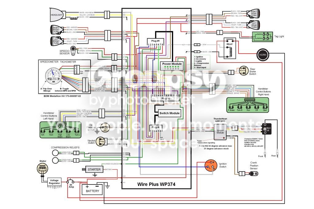
Also saw a post and requested a copy of a WP374 schematic one of the members came up with. Anyone have a copy they could send me?
Thanks
Step #9. Route the red wire form the power module to the SILVER (Aux) side of the 30 Amp breaker. Trim to length....I presume the original wiring that was on the 30A breaker still get connected? Black to Silver post & Red to Copper post on the breaker?
Step #31. Cut grey wire off of the 2004 EHC module. Plug into position 3 of plug #3.
At this point during the installation I have NO GREY wires left to cut on the EHC module!
Step #34. Using a butt splice from the kit, combine the following tach wires: a. Green wire, EHC position 20. & b. Yellow wire, EHC position 21.
At this point during the installation I have NO YELLOW wires remaining to be cut!
When cutting wire from EHC connector I used a magnifying glass and performed a continuity test from pin side of connector to the wire side of connector. What the hell am I missing hear??
I also received a bag with a triangular shaped Deutch connector (3-pin). Is this for the new key switch??
For those of you who have done the install. Did you solder the wires in the butt and spade connectors or did you crimp???
I have not been on the bike in about a year and am looking forward to getting her up and running. Any help would be appreciated.
Also saw a post and requested a copy of a WP374 schematic one of the members came up with. Anyone have a copy they could send me?
Thanks