Texas_Rigid
Member
After installing the Baker open primary on my '06 K9, I thought I'd post the instructions with some supplemental notes. Overall the instructions were good, but a couple of things came to light after the install that I felt could be helpful to someone else. Below are the instructions as Baker wrote them, with some changes for formatting (simple cut and paste didn't work from their PDF) and my notes highlighted in green.
Any reference to images below is for the pictures included in the Baker instructions. I'm no writer, you still want their instructions even if you're reading this!!!
From Baker:
Skills, knowledge, and tools:
No special tools are required to complete the installation. However the following common mechanic’s tools are necessary to do the job in addition to standard every guy tools.
A 2005-up Big Dog Service manual should be referred to for removal of the stock wet primary.
Please refer to the 2005-up Big Dog service manual for disassembly and removal of the stock primary drive.
Forum member Marky-Marc does a couple of excellent videos on YouTube for primary disassembly:
Big Dog Complete Primary Disassembly Part 1
Big Dog Complete Primary Disassembly Part 2
The short version of the disassembly process goes as follows:
Any reference to images below is for the pictures included in the Baker instructions. I'm no writer, you still want their instructions even if you're reading this!!!
From Baker:
Skills, knowledge, and tools:
No special tools are required to complete the installation. However the following common mechanic’s tools are necessary to do the job in addition to standard every guy tools.
- Torque Wrench (ft. lbs & in. lbs)
- ½” impact gun (PneuMatic or electric)
- 1 3/6 and 1 5/6 Sockets (I used 30mm & 32mm, but I still love America!)
- Plastic or rubber mallet
A 2005-up Big Dog Service manual should be referred to for removal of the stock wet primary.
Please refer to the 2005-up Big Dog service manual for disassembly and removal of the stock primary drive.
Forum member Marky-Marc does a couple of excellent videos on YouTube for primary disassembly:
Big Dog Complete Primary Disassembly Part 1
Big Dog Complete Primary Disassembly Part 2
The short version of the disassembly process goes as follows:
- Disconnect the battery. Remember: ground cable first; use a 10mm wrench
- Shut off the fuel at the tank petcock
- Drain the primary oil. Remove the drain plug with a 3/16” allen.
- Remove the clutch adjust access cover on the drive pulley cover on the right side of the bike. The access cover comes off by hand, like an oil filter. Loosen the clutch rod jam nut and draw the pushrod out an inch or so. Complete removal of drive pulley cover makes starter removal much easier. It’s only (3) bolts!
- Remove the following parts from the primary roughly in the following order:
- Starter; 9/16 hex for battery feed (I did not remove wire from starter, only from battery) and 2 X 3/8-16 with 5/16 allen for flange. It is not necessary to remove the starter from behind the transmission. Let starter lay on back of transmission case during O.E. primary removal and belt drive installation.
- Outer primary; 14X1/4-20 cap screws, 3/16” allen
- motor sprocket nut; 1-5/16 socket with impact. Set nut and washer aside. It will be re-used on the belt drive motor pulley
- Chain adjustment shoe nut; 9/16” socket
- Remove throwout bearing on clutch with medium size snap ring pliers
- Remove clutch nut with 1-3/16” socket and ½” impact gun. NOTE: lefthand threads, clockwise to loosen
- Remove clutch, motor sprocket, and chain as a complete assembly
- Remove the 8X5/16-18 hex bolts from the inner primary. Bend back locktab wings and use a ½” socket to remove bolts.
- Remove the 2X5/16-18 cap screws from the outside front of the primary with a ¼” allen
- Loosen (just a couple turns) the six bolts that hold the transmission to the frame with an 5/8 wrench so the transmission is free to move and align with the new belt drive motor plate. I had to drop the shocks on my K9 so I could get at the bolts with a socket. The tranny bolts are sort of recessed in the mount plate, no way a wrench was grabbing hold with enough force to break em loose. I first removed the protector plate under the front shock bolts, then removed on hte back shock bolts. This lets the shocks drop down out of the way. This was one of the biggest PITA of the whole process.
- Remove the primary o-ring from the engine case so any water that enters that area can drain out.
- Remove the six small o-rings from the transmission case, not required.
- Leave the one o-ring on the snout of the transmission to help center the motor plate during installation
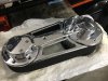
- Remove Synchronous belt drive content from shipping box. Remove all six flat head screws from both pulley covers Remove the bolts on both sides of pulley covers, not the bolts for the outer bearing support. Will save some time moving forward. Outside bearing support assembly, motor sprocket, and clutch assembly will be separate.
- Clean and degrease the motor and transmission areas.
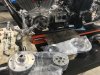
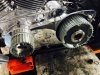
- Install the motor plate assembly onto the engine and transmission (Figure 8) and loosely tighten the 5X5/16-18 cap screws and 5X5/16-18 hex bolts on the motor and transmission with red loctite using a ¼” allen/1/2” socket. Note, the stainless steel cap screws go on the engine. No beer breaks here because the red loctite will set up.
- The 6X7/16-14 hex bolts on the bottom of the transmission can be tightened down now with a 5/8 wrench.
- Lastly, torque all of the 5X5/16-18 cap screws and 5X5/16-18 hex bolts to 18 ft-lbs with a ¼” allen/1/2 socket. The motor plate installation is complete.
- This tightening ritual/procedure is required because the Big Dog system relies on the snout of the transmission to orient the complete drivetrain and no shims under the transmission are required.
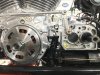
- Install the new clutch assembly to the transmission mainshaft using the LH clutch nut and washer provided. Using red loctite, torque the nut to 80 ft-lbs.
- Install the front motor pulley and lightly tighten the nut. Using a straight edge along the outside face of the pulley and a pair of calipers, check to see that the two pulleys are axially located within .030” of each other. Use the motor plate as a zero reference for measuring the pulley locations. Motor sprocket shaft shims are supplied with the kit. Select the appropriate shim or shims. Once the axial pulley location is confirmed, remove the motor pulley nut and torque it to 150 ft-lbs with red loctite. The picture in the instructions tells 1,000 words
- On a bench, screw the outer bearing support standoffs and locking nuts as far into the outer support as they will go with blue loctite. Temporarily install the outer support to the pulleys with 3 flathead screws in each pulley. Extend (loosen) the stand offs until they lightly seat into the motor plate then adjust the lock nut down. The standoff height is set. Remove the outer support from the pulleys.
- Install the starter pinion cover with blue loctite on the three flat head screws and torque them to 100 in-lbs. I don't know why this step is here in the order. I left the cover off until the very end to ensure my starter pinion was aligned
- Install the clutch throwout bearing assembly with the snap ring provided.Adjust the clutch pushrod from the right side. Lightly screw in the clutch rod with a 7/32 allen until it stops and back it out 1/3 turn. Set the 7/16-20 jam nut and reinstall the clutch adjust cover. Test for clutch actuation and feel. If there is excessive or no freeplay at the clutch lever, make appropriate adjustments at the clutch cable adjuster. Again, not sure why this step is here in the order. I fully assembled the primary, reinstalled starter, put my drive pulley cover back together on the right side of bike, then adjusted clutch. Lots of info on the forum for clutch adjustment that helped me tremendously.
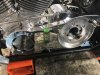
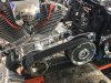
- Install the belt over the pulleys. Slowly work it over the two pulleys and move it inboard with a top to bottom rocking motion. Use a rubber or plastic mallet to help it on if necessary. If it does not go on even with persuasion from the mallet, call BAKER tech department. Do not force it on. make sure the belt is inboard of the outer pulley surfaces. I used a mallet, it was snug but not impossibly tight
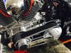
- Install the outer bearing support to the motor pulley and lightly install the six attaching screws. If the clutch outer bearing support cover will not readily slip into the clutch pulley, then start two screws at the bottom and gently pull the bottom of the cover into the clutch pulley. If the clutch cover still does not want to slip in the clutch pulley, then the spark plugs from the engine should be removed to allow the clutch to be rotated to walk the pulley cover on just like walking a chain onto a bicycle sprocket.
- With both pulley covers in place, install all six flat head screws in each pulley with blue loctite and torque them to 100 in-lbs. With the bearing support firmly attached to the pulleys, install the two long flat head screws through the stand offs and into the motor plate with 100 in-lbs of torque and blue loctite.
- Some oil may be lost from the transmission mainshaft area (you will see it when the original clutch comes off) so be sure to recheck the oil level or better yet, change the oil in your BAKER transmission at this time.
- Reinstall the starter (steel dowel included in parts but not referenced in directions-this installs in between starter and motor plate-its not a tight fit so a drop of glue on the starter side is handy to keep it in place while bolting starter back up-its a cramped space but can be pushed in guide hole without complete removal of starter-also don’t forget ground lead from battery to starter flange), connect the battery and take it for a test drive. If you have any questions or concerns, call BAKER tech department.
")