Speed sensor output?

Energy One

ChopperJeff

Active Member
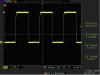
Does anyone happen to know what exactly is the output of the speed sensor, as in square wave, sine wave, or what, and the output levels?

I ask for two reasons. First of all, I'd like to throw together a simple circuit that simulates the speed sensor's output so I can use it to determine whether a speedometer has gone bad. Secondly, I'm looking at purchasing a new speedo that comes with zero miles on it, and I'd like to be able to "spin it up" to the correct mileage.

Thanks!
 

LDO

The Cleaner
Troop Supporter
Jeff,
I know this doesn't actually answer your question but can't you send your new speedo out to BD to get it 'spun up' to your current mileage?

Reason I mention this is because I believe Ray did this a while back when he replaced his speedo.
 

ChopperJeff

Active Member
Thanks LDO, but I emailed Big Dog asking them if they could set the mileage on a new speedo, and they replied saying that they cannot unless it's purchased from an authorized dealer. The one I was looking at buying, but not getting, was an eBay item. Now just what exactly Big Dog means by "authorized dealer", I don't know. I suppose they mean one that is authorized to sell Big Dog parts, but what's that got to do with having them set a speedo's milieage, especially if it's a Big Dog part?

Oh well, maybe they don't like the idea of people getting Big Dog parts from non-Big Dog dealers.
 

Raywood

The Pirate
Staff member
Calendar Participant
Troop Supporter
Oh well, maybe they don't like the idea of people getting Big Dog parts from non-Big Dog dealers.
Could be a requirement by DOT too! They make you sign and affidavit when they do your speedo.

For the sensor you should pm Ohmster or Night Rider and see what they say.

:cheers:
 
Night rider...you turned me into a talking car, hopefully I am the original Kit and not the awful new one that is some type of transformer or something :)

I have attached an Oscope shot of the signal. This is the signal at ~60mph. The 2004 is a bit different but for what you are doing this should work. If you have access to a function generator you can create a 5v square wave with about a 50% duty cycle, crank up the frequency to make it go faster. If you go over about 5khz I think it is the speedometer will not respond. Keep it at about 1khz and you'll be fine. If you have problems let me know, I can program it for you.
 

Attachments

Last edited:

Raywood

The Pirate
Staff member
Calendar Participant
Troop Supporter
Night rider...you turned me into a talking car, hopefully I am the original Kit and not the awful new one that is some type of transformer or something :)
Ha ha, sorry dude. I'll get it right next time. At least I was thinking of you!! :D
 

BigDogBro1

Made in the USA
You will need to test with an oscilloscope and probe the sensor leads with the probe ground connected to battery ground while the circuit is in operation on the bike. If the sensor is a two wire then it's likely to be a sinewave signal output.

Nice work Night Train!

IntelliDash :: Performance Digital Gauges
 
Last edited:

ChopperJeff

Active Member
Thank you Night Train for the scope output! I would assume the signal swings from 0v up to about 8v, and not going negative. I may just build a simple Multivibrator circuit and use it in lieu of a signal generator. I'd like to complete this project with as little cost as possible.
 

ChopperJeff

Active Member
Managed to throw together a simple circuit that simulates the output of the speed sensor, so now I can "spin up" my speedo! However, it's currently set at about 360 MPH, meaning the speedo is pegged while it's running. I can easily set it down to a lower speed, but it's nice "as is" since it will take a shorter time to get up to the 52,000 miles I need.

Does anyone know if having the speedo "pegged" for a number of hours will do any harm?

By the way, this simple circuit can also be used to verify that your speedo is functioning correctly. Once I get some connectors to plug into the wire harness, I can offer it to anyone who wants to try it out. As it stands right now, I've got it T'd into the wires going to the speedo.
 

Raywood

The Pirate
Staff member
Calendar Participant
Troop Supporter
Managed to throw together a simple circuit that simulates the output of the speed sensor, so now I can "spin up" my speedo! However, it's currently set at about 360 MPH, meaning the speedo is pegged while it's running. I can easily set it down to a lower speed, but it's nice "as is" since it will take a shorter time to get up to the 52,000 miles I need.

Does anyone know if having the speedo "pegged" for a number of hours will do any harm?

By the way, this simple circuit can also be used to verify that your speedo is functioning correctly. Once I get some connectors to plug into the wire harness, I can offer it to anyone who wants to try it out. As it stands right now, I've got it T'd into the wires going to the speedo.
52,000............ :eek: :eek: :eek:

I need to get on the road. Can't let you catch up you know! :lol:
 

chacha

Chaff Your EHC!!
Calendar Participant
Nice work ChopperJeff. Got no data to support it, but suspect that continued max stress on the motor driving the needle can't be good for it.

You may want to dial it back or drop it out of hyper-drive every couple of hours to let it recal on power-up.

At 52000 miles;

144.444 hours at 360 mph ==> 6 days
433.333 hours at 120 mph ==> 18 days!
 

ChopperJeff

Active Member
Yeah, I think I'll play it safe and dial it back to 120 MPH. In the mean time, I'll see about getting a more permanent circuit built, with the correct connectors and all, so I'll have something available for testing the speedo if I suspect it's taken a dump sometime down the road. Should act as a good diag tool! I'll also make it available to people who want to try it out... at a small fee of course. Or if asked, I can supply the parts list and schematic.
 
Top