
Dog won't start: puzzled
- Thread starter BigDog2005_chopper
- Start date


BigDog2005_chopper
Member
Battery voltage DOSNT DROP.Does the battery voltage drop when you try to start
So i took out the 5 pin relay from with in the the pdm module. and youtubed how to test it.
it clicks so it works.
Now what the heck do i check why im getting no power to starter/ soloid?
by no means am i a mechanic. but i'm learing. lol
BigDog2005_chopper
Member
thanks so much. I haves learned how to bench test my backup (rebuilt starter / solinoid)
so now i want to buy replacment 5 pin relays for my pdm model. I"M in north america. and took my old one to Napa and they had no part number to search thus dead end.
I belive this is a micro automotive relay and now need to find parts number or cross refernence # so napa can supply me with extra's
i'll post some pics.

and
 [/URL][/IMG]
and
http://i24.photobucket.com/albums/c15/nealmccallum/Mobile%20Uploads/20140907_205557_zpsnowvhq4k.jpg
so now i want to buy replacment 5 pin relays for my pdm model. I"M in north america. and took my old one to Napa and they had no part number to search thus dead end.
I belive this is a micro automotive relay and now need to find parts number or cross refernence # so napa can supply me with extra's
i'll post some pics.
and
and
http://i24.photobucket.com/albums/c15/nealmccallum/Mobile%20Uploads/20140907_205557_zpsnowvhq4k.jpg
No, thank you. This is how I school myself replacing parts as if I owned the bike, had no clue about it, but just enough so you can't figure it out like why you following my lead? Hi haven't a clue about said bike!
G8V-RH-1C7T-R-DC12 Omron Electronics | Automotive Relays

 Napa, but this is more chasing one online.
G8V = Got me 8 volts or less as a working unit.
RH = This is my 'Rated Humidity' as in, how wet do I have to be to short out?
1C7T = Contact pin structure (swapping) as opposed to a 1A7 type and that pin change.
dc12 = Minimum volt carry of the unit.
G8V-RH-1C7T-R-DC12 Omron Electronics | Automotive Relays
Napa, but this is more chasing one online.G8V = Got me 8 volts or less as a working unit.
RH = This is my 'Rated Humidity' as in, how wet do I have to be to short out?
1C7T = Contact pin structure (swapping) as opposed to a 1A7 type and that pin change.
dc12 = Minimum volt carry of the unit.
BigDog2005_chopper
Member
Thanks for the link.
but i want to buy local if possible.
that site was to charge me 18.00 usd for min surcharge for under 100 dollars (no thanks)'
I only need the cross ref # to buy from Napa OR someother local group.
anyone?
but i want to buy local if possible.
that site was to charge me 18.00 usd for min surcharge for under 100 dollars (no thanks)'
I only need the cross ref # to buy from Napa OR someother local group.
anyone?
Jwooky
Well-Known Member
Dude seriously, I don't know if you don't know how to talk, or you think its cute.:down:No, thank you. This is how I school myself replacing parts as if I owned the bike, had no clue about it, but just enough so you can't figure it out like why you following my lead? Hi haven't a clue about said bike!
G8V-RH-1C7T-R-DC12 Omron Electronics | Automotive Relays
G8V = Got me 8 volts or less as a working unit.
RH = This is my 'Rated Humidity' as in, how wet do I have to be to short out?
1C7T = Contact pin structure (swapping) as opposed to a 1A7 type and that pin change.
dc12 = Minimum volt carry of the unit.
Either way, its not helpful when you take what are generally topics folks don't understand, and are often complicated and attempt to explain them in a way that is unintelligible.
IMHO you are just clogging up the site with nonsense, and confusing people. Either speak intelligibly or just stay out of topics.
bearman
Active Member
Just because it clicks doesn’t mean it is good, the contacts inside the relay could be bad. Even if you use a multi meter to check the continuity across the “load” terminals when powering the “coil” terminals, the contacts could still be bad enough to only let a small amount of current thru but not enough to make the starter work.
The best way to test a relay is to swap it out with a known working relay and see if anything changes. But if you can hear it click when testing it off the bike, you should also be able to hear it click on the bike when you hit the start button.
To test if you are getting voltage through it on the bike, check for voltage at the green wire on the starter solenoid when the start button is pressed.
With the other problems you are having, it sounds like your HCI module is bad, or not getting voltage from the PDM module. Check the wiring on the bottom of the PDM and make sure it is all firmly connected.
You didn’t mention if you had done this so I’ll just go ahead and say to first make sure that your circuit breaker (or 40A fuse) to the voltage regulator is good and that you have voltage on both sides of it. The PDM diagram shows power to the PDM from both sides of this breaker/fuse.
Pull all your fuses and make sure the terminals are relatively clean then re-install and check for voltage to both sides of all your fuses.
Checking the HCI.
If you have voltage to the fuses next check for voltage at both red wires on the 12-wire connector going to the HCI (position 1 is from the PDM and position 7 is to the Run switch). Do this with the key on and everything connected, pierce the wire with the point of the multi-meter probe (be sure to cover the pierce later with some liquid tape to prevent corrosion). If you don’t have voltage to position 1 then you have a problem with the wiring between the PDM and the HCI. If you have voltage to position 1 but not to position 7, the HCI is bad. If you have voltage to both then go to next step.
If you have voltage there then hit run button and check for voltage on the red wire at position 7 on the 8-wire connector. This is the power to the ignition and to the coil side (red wire) of the starter relay. You can check this by pulling the relay and checking for voltage at the red wire socket. There should also be a red LED on the ignition module that is on. If you don’t have voltage at either of these then pierce the wire on the HCI side of the connector and check there. If no voltage here after pushing the run switch with the key on then the HCI is bad or the wiring or run switch is bad.
Options
1. Replace the HCI. (I think Badlands and Wire Plus both have a hand control module that can be made to work and still keep the PDM module.)
2. a) Jump the #7 wire on the HCI 8-wire connector to the #1 wire on the HCI 12-wire connector and see if it starts. This bypasses the run switch (and internal HCI relay) and powers the ignition and coil side of the starter relay with the key switch. I’m not sure if defeats the off switch also, but if it does and it starts you will just have to kill it with the key. It also bypasses the safety system that disables the starter when the engine is already running, so if you hit the start button (instead of the blinker) with the engine running it will grind the starter (not good).
2. b) If you also jump the #10 wire (orange) to the #1 wire on the 12-wire connector your brakes should work with the key on.
2. c) If you then also jump the #6 yellow wire on the 6-wire connector to the same #1 wire on the 12- wire connector you will have low-beam headlight. It will not shut off when the starter is cranking, so if you have problems starting, you might need some kind of switch here to help keep the battery output at its best when starting.
2. d) YOU WILL NOT HAVE TURN SIGNALS. Even if you powered them by jumping wires and bypassing the HCI, they would not blink. So if you do all this and have no blinkers, you should not be trying to hit the right turn button and accidentally hitting the start button.
Last edited:
IMO you wasted a post. Ignore me or counter my diagnosing/help. Until you are up on the bike as Mike and that blue bagger figuring out that ferrite, you need to sit this one out or continue the diagnose.Dude seriously, I don't know if you don't know how to talk, or you think its cute.
IMHO you are just clogging up the site with nonsense, and confusing people. Either speak intelligibly or just stay out of topics.
My cute says you better have some common sense so it makes sense. I gave the house a compliment and you kick me in the teef? Shadup and sit down! This is out of your league you start in with the drama and not help the OP. Runner UPPER!
Now go cry to the post police. Grow UP!
Mickeetwo
Guru
Just because it clicks doesn’t mean it is good, the contacts inside the relay could be bad. Even if you use a multi meter to check the continuity across the “load” terminals when powering the “coil” terminals, the contacts could still be bad enough to only let a small amount of current thru but not enough to make the starter work.
The best way to test a relay is to swap it out with a known working relay and see if anything changes. But if you can hear it click when testing it off the bike, you should also be able to hear it click on the bike when you hit the start button.
To test if you are getting voltage through it on the bike, check for voltage at the green wire on the starter solenoid when the start button is pressed.
With the other problems you are having, it sounds like your HCI module is bad, or not getting voltage from the PDM module. Check the wiring on the bottom of the PDM and make sure it is all firmly connected.
You didn’t mention if you had done this so I’ll just go ahead and say to first make sure that your circuit breaker (or 40A fuse) to the voltage regulator is good and that you have voltage on both sides of it. The PDM diagram shows power to the PDM from both sides of this breaker/fuse.
Pull all your fuses and make sure the terminals are relatively clean then re-install and check for voltage to both sides of all your fuses.
Checking the HCI.
If you have voltage to the fuses next check for voltage at both red wires on the 12-wire connector going to the HCI (position 1 is from the PDM and position 7 is to the Run switch). Do this with the key on and everything connected, pierce the wire with the point of the multi-meter probe (be sure to cover the pierce later with some liquid tape to prevent corrosion). If you don’t have voltage to position 1 then you have a problem with the wiring between the PDM and the HCI. If you have voltage to position 1 but not to position 7, the HCI is bad. If you have voltage to both then go to next step.
If you have voltage there then hit run button and check for voltage on the red wire at position 7 on the 8-wire connector. This is the power to the ignition and to the coil side (red wire) of the starter relay. You can check this by pulling the relay and checking for voltage at the red wire socket. There should also be a red LED on the ignition module that is on. If you don’t have voltage at either of these then pierce the wire on the HCI side of the connector and check there. If no voltage here after pushing the run switch with the key on then the HCI is bad or the wiring or run switch is bad.
Options
1. Replace the HCI. (I think Badlands and Wire Plus both have a hand control module that can be made to work and still keep the PDM module.)
2. a) Jump the #7 wire on the HCI 8-wire connector to the #1 wire on the HCI 12-wire connector and see if it starts. This bypasses the run switch (and internal HCI relay) and powers the ignition and coil side of the starter relay with the key switch. I’m not sure if defeats the off switch also, but if it does and it starts you will just have to kill it with the key. It also bypasses the safety system that disables the starter when the engine is already running, so if you hit the start button (instead of the blinker) with the engine running it will grind the starter (not good).
2. b) If you also jump the #10 wire (orange) to the #1 wire on the 12-wire connector your brakes should work with the key on.
2. c) If you then also jump the #6 yellow wire on the 6-wire connector to the same #1 wire on the 12- wire connector you will have low-beam headlight. It will not shut off when the starter is cranking, so if you have problems starting, you might need some kind of switch here to help keep the battery output at its best when starting.
2. d) YOU WILL NOT HAVE TURN SIGNALS. Even if you powered them by jumping wires and bypassing the HCI, they would not blink. So if you do all this and have no blinkers, you should not be trying to hit the right turn button and accidentally hitting the start button.
Excellent post Bearman.....Thanks for the info on checking the HCI :2thumbs: Some of us are still sporting the PDM. And the info on getting another HCI module if ours quits working. I too think his HCI could be bad, thats the reason I posted the wiring schematic for the PDM. Your post needs to be a STICKY or in the HOW-TO forum. Again thanks for taking the time to post the info on the HCI. Some of us PDM'ers really appreciate it.
Last edited:
francoblay1
The Spaniard
This one is Bullet Proof.... 

Good Info Bearman :2thumbs::2thumbs::2thumbs:
Good Info Bearman :2thumbs::2thumbs::2thumbs:
bearman
Active Member
You’re welcome.
Just trying to give a little back and hopefully help someone get back to riding.
I know how sometimes electrical schematics can look like an alien language, I usually understand them pretty well, it’s the English that I have more problems with (and English is my primary/only language).
Near as I can tell, the start circuit on the PDM scooters work like this;
Turning on the key activates a relay in the PDM that sends power to the HCI. Hitting the run switch then sends power to the ignition and the coil side of the starter relay, from the coil side of the start relay it goes to the start switch on the bars. When you hit the start switch it closes the circuit to ground (back to the battery) which activates the starter relay.
bearman
Active Member
I don’t think your problem is your relay but since you asked….
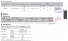
The old relay has the part number right on it, I can see it in your picture, G8V-RH-1C7T-R-DC12 (I circled it in my attached pic of the data sheet).
It also says on the datasheet that it is a standard type, which basically means that there are probably other companies that make a compatible relay that will fit the same socket.
But you shouldn’t just replace it with one that fits in the connector, it is important to replace it with a relay that has nearly the same power consumption (or less) and also that has a resistor on the coil side (since the old one does). And of course it is important to get one that has nearly the same current capacity on the switching contacts (this one has 35A on the Normally Open side, which is the important one in this situation).
You find the power consumption from the datasheet. I have attached a screen shot of part of the datasheet that was linked to the webpage that Sven provided the link for.
This particular datasheet has a typo, where it says power consumption in mA (miliAmps) it should be mW (miliWatts). Amps is current, Watts is power (Watts = Amps x Volts). In this case 0.141 Amps x 12V = 1.69 Watts
Our hand controls are supposedly only rated for about 1.25 Watts and this one is rated at 1.69 Watts, but since this is the one that came with the PDM kit I have to assume it is safe to keep using but I for sure would not use anything that uses more. The bigger (about an inch square) automotive relays use around 2 Watts.

That just goes to show you how far NAPA has fallen....... i want to buy replacment 5 pin relays for my pdm model..... took my old one to Napa and they had no part number to search thus dead end.......
The old relay has the part number right on it, I can see it in your picture, G8V-RH-1C7T-R-DC12 (I circled it in my attached pic of the data sheet).
It also says on the datasheet that it is a standard type, which basically means that there are probably other companies that make a compatible relay that will fit the same socket.
But you shouldn’t just replace it with one that fits in the connector, it is important to replace it with a relay that has nearly the same power consumption (or less) and also that has a resistor on the coil side (since the old one does). And of course it is important to get one that has nearly the same current capacity on the switching contacts (this one has 35A on the Normally Open side, which is the important one in this situation).
You find the power consumption from the datasheet. I have attached a screen shot of part of the datasheet that was linked to the webpage that Sven provided the link for.
This particular datasheet has a typo, where it says power consumption in mA (miliAmps) it should be mW (miliWatts). Amps is current, Watts is power (Watts = Amps x Volts). In this case 0.141 Amps x 12V = 1.69 Watts
Our hand controls are supposedly only rated for about 1.25 Watts and this one is rated at 1.69 Watts, but since this is the one that came with the PDM kit I have to assume it is safe to keep using but I for sure would not use anything that uses more. The bigger (about an inch square) automotive relays use around 2 Watts.
Attachments
-
 87.4 KB Views: 42
Last edited:
BadDawg Bill
Well-Known Member
You’re welcome.
Near as I can tell, the start circuit on the PDM scooters work like this;
Turning on the key activates a relay in the PDM that sends power to the HCI. Hitting the run switch then sends power to the ignition and the coil side of the starter relay, from the coil side of the start relay it goes to the start switch on the bars. When you hit the start switch it closes the circuit to ground (back to the battery) which activates the starter relay.
No wonder there are so many electrical problems on these dogs...