V-TWIN CONNECTIONS

07bigdog

07BIGDOG
Is Dave at v-twin connections still in business? I contacted him with a technical question and never received an answer. Checked on his site and it is down due to maintenance. I need help to install a horn relay kit with an older PDM kit. Not sure where one of the wires hooks up. Can anyone else out there help me?
 

Jwooky

Well-Known Member
Haven't heard anything from him for a while.

What is your question?

Typically the the relay setups are pretty simple. It has a low current control side with power and ground and the button interrupts the ground side.

The load side of relay then powers the device.
 

07bigdog

07BIGDOG
Hope you can help me. The long wire goes into pin position 1 of the J1 connector on the master harness after you remove the existing wire in that location. The problem I have is where does the short wire go? it says to install in position 3 of the J1 connector on the HCI harness. No where does it tell you to remove the existing wire from that position. If you remove the existing wire from that position and insert the short wire, the whole electrical system on the bike was dead. Had nothing when the key was turned on. Re-installed the old horn relay that came with the bike and everything works. I'm not sure if i'm installing the short wire in the right spot.
 

Jwooky

Well-Known Member
Sorry I don't have specific knowledge of the pinout of the PDM system. I was offering functional knowledge that would hopefully offer some help.
 

bearman

Active Member
Sorry It took so long to put this up, I couldn't find my PDM diagram.
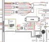
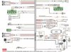
Not sure if this helps. The wiring diagram I have is for a “rev C” PDM. But it looks like the horn low amp “control circuit” comes from pin 1 on the PDM module (where the fuses are), then the diagram shows it just goes into the “Master Harness”.

I believe it should go into pin 3 of the HCI module 12 position connector (the HCI should have 3 connectors, a 12 pin and two 8 pin).

It looks like this connector has a gray wire going to the horn button on the wire harness side and nothing on the HCI side. I think this is where you should hook your short wire, in this “open pin” opposite of the gray wire.

The 2005 up hand controls operate on a grounding function, so if you attach your “long wire” to the gray wire (from the PDM) and the “short wire” to the gray wire (to the HCI) going to the horn button on the controls this should make the “control circuit” function and operate the horn relay.

The PDF i have is too big to upload so I took some screen shots of it. I will try to email it to you if your email is listed here.


Attachments

07bigdog

07BIGDOG
Bearman, I finally installed the horn relay kit. Would really like to thank you for the wiring schematic and instructions. Wouldn't have been able to complete without you.
 

BadDawg Bill

Well-Known Member
Bearman, I finally installed the horn relay kit. Would really like to thank you for the wiring schematic and instructions. Wouldn't have been able to complete without you.
That's what good forums are all about. good job Bearman. :up:
 

Raywood

The Pirate
Staff member
Calendar Participant
Troop Supporter
bearman hooked you up. The short wire goes to ground. If the relay quit just swap it out with the other relay next to it to test it. If it still doesn't work then I would check the connection at the handlebar control
 

07bigdog

07BIGDOG
Thanks guys but all working right now in the shop. Haven't gone for a ride yet, but while engine running and honk the horn, the bike keeps running where before it would shutdown.
 
Top