
DRBarnhart
Insert title here...
You turn that plate and the timing will follow. Don't believe me? Give it a try...hey dennis,i know thats where the timming is set but is the timming on these dogs oretty much set and not adjustable

Dennis


You turn that plate and the timing will follow. Don't believe me? Give it a try...hey dennis,i know thats where the timming is set but is the timming on these dogs oretty much set and not adjustable

i won't be able to tell the diff mine wont start as isYou turn that plate and the timing will follow. Don't believe me? Give it a try...
Dennis
I can appreciate that!! I also can appreciate a guy like you that has the tenacity to stick with his troubleshooting until he finds the problem. :2thumbs:i have a mutimeter thats about my knowledge of that. lol I think i'll waite till the morning my mind is blown and my back is shot. I'm sure its the Cam sensor cause i have no light.

And if you turn it too far from where it is right now it will never start!!! :lol:i won't be able to tell the diff mine wont start as is

Yeah thanks man would be easier over the phone. I'll give it hell in the morning please stay tunned or shoot me you phone#. might be a hell of alot easier. Either way thanks guysAnd if you turn it too far from where it is right now it will never start!!! :lol:
Dennis
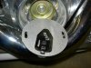
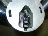
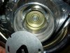
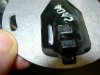
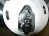
It looks OK but that doesn't mean that it is.Looks Fine. Now what? How can I Test it?
I don't know what an RX1 scale isIt looks OK but that doesn't mean that it is.
Here's a couple of quick checks you can do with your multimeter while the sensor is out and blowing in the breeze...
Coming out of the ignition module there should be a couple of pigtails, one with four wires and the other with three. The three wire connector goes to your cam sensor and should have a red, black, and green wire in it. Now take your multimeter, set it to the RX1 scale, put the black meter lead on the sensor plate and on the connector that goes to the sensor (not the side that goes to the ignition module!) then with the red lead check for continuity from the backing plate to each of the wires individually. If you get any value other than "open" the sensor is bad.
Now put the red multimeter lead on the green wire coming from the sensor and your black lead on the black wire coming from the sensor, you should get an "open". Switch the leads from the meter (black for red, red for black), you should get something like 300K to 750K ohms, if you don't the sensor is bad.
I have to go to work now but I'll try and check on your progress later.
Good luck! :2thumbs:
Dennis
PS If I knew what type of multimeter you had I could get a little more specific on the settings.
PPS Did you ever check the coil like I mentioned earlier?
When you measured this did you have your meter on the "200" setting? (It's at about the 10 o'clock position inside the ohms scale.)Now when i test the coil, i get 3.3 ohms for the sides and 11.47 ohms where the plug wires go
see below for a possible explanation...DRBarnhart said:Now put the red multimeter lead on the green wire coming from the sensor and your black lead on the black wire coming from the sensor, you should get an "open".
That'll work if there's "K" lurking somewhere on your meter's screen!for this part of it i get 674DRBarnhart said:Switch the leads from the meter (black for red, red for black), you should get something like 300K to 750K ohms, if you don't the sensor is bad.
Nothing as in no number? Maybe a "OL" or something? If that's the case then you have an "open" which means your sensor passes this test too.I get nothing when i do this.DRBarnhart said:red lead check for continuity from the backing plate to each of the wires individually. If you get any value other than "open" the sensor is bad.