Engine light glows when bike is running

olddog58

Member
I had the BDM PDM installed on my 2008 K9. Original EHC died back in October 2011. Finally got the bike back Jan 11...
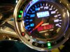
Now my engine light stays glowing when the bike is running. Managed to ride the bike about 50 miles when I picked it up, but it was sunny and I didn't notice the light glowing until sunset. Battery was dead after two days sitting.
I've run most all the tests... Battery charged full to 12.8 volts. drops 0.5 volts when the ignition is turned on. reports about 14 volts when the bike is running. Shop checked the battery (fine), checked the Voltage Regulator (fine)... so what causes the engine light to glow? It's not on bright like when you first turn on the ignition and run switch...
Any good electricians out there???
 

Attachments

Fibersnake

Banjo Playing PsychoBilly
Is this an EFI Bike I take it? If so, probably related to something on that side, possibly just need a rest of something. Not sure not very familar with the EFI circuits. so do not know what would trip a Engine Light.

Wish I could help more.
 

Fibersnake

Banjo Playing PsychoBilly
Looking at the scematic, the EFI Controler is only connected to the PDM via 1 wire and that is from Bank Sensor Green wire to #9 pin on EFI Controller. All check engine function are coming from EFI Controller and not new PDM and if not mistaken (other than the one wire from Bank Sensor) the only thing in common is the Main Harness.

Unless the installer F- that up and shorted it someway, the only points would be at the 2 pin connectors going to the Annuciator Board (Tach Board).

So if you want to try to trouble shoot it yourself, only thing I would suggest at this time is to insure that it is not an actual fault being sent from the EFI Controller. To do such, if you are handy and know basic electical, you could disconnect the 2 pin connector from the tach board, and move it aside, then if possible, start the bike and then check with mulitmeter on DC volts, first to the gray wire on the 2 pin connector (engine check) to a ground and see if you get current (if so you are getting a signal being feed to it form somewhere). Also check the connector on the 2 pin and make sure that one of the pins did not get bend and possibly touching the other.

If by chance you disconnect the 2 pin to the tach board and start it and it shows the light, than you may have a bad board or it may be shorting out slight on the cicuits due to mositure, corrosion etc. This would laso be a goo time to get eletrical contact cleaner and mositure displacing-protector spray and clean the backside of the tach board coat same with mositure displacing and protector. Also insure that connectors have a little bit of dielectric grease in the connectors.

If that is the case, then you can go to EFI interface (with the 2 pin still disconnected) and probe pin #8 with multi meter on DC and to ground and see if there is a signal there. If so you more than likely have a fault being sent from EFI and that could be anything from O2 Sensor, termistor fule injector, etc.

To be on safe side and to verify that there is not a short in the harness, you could make sure the bike is shut off, disconnect battery for safety (Neg first-then positive, reverse on hook up). Disconnect the EFI Interface from EFI to harness, disconnect the 2 pin at tach board, take multimeter, check the gray wire for continuity from end to end, if good, next check gray wire to ground, (should have none), then to be on safe side check gray wire to white (low fuel-since they come to common connector) and make sure you have no continuity between them that would indicate short.

That is about all I can suggest at this time, but make sure that you have done all the trouble shooting for the EFI first and read the details to that, to make sure the eng light is not being displayed due to it is supposed to be cause of error or problem being sent from EFI controller, or possibly due to when they discconect circuit and the circuits need to be reset from loss of power.

Good luck.
 
Last edited:

BigDogBro1

Made in the USA
Updated: SORRY MY FIRST POSTING ANSWER WAS WRONG...I failed to notice that the LEDs for the ENGINE CHECK and LOW FUEL are common tied to 5 volts.

If it's installed correctly, then it could be.......

On an EFI bike it could be the PDM KIT pull-up resistor for the EFI Check Engine LED signal is too high resistance thus not allowing the S&S EFI module circuit to turn OFF the LED completely.

I think the EFI controller outputs were OPEN COLLECTOR type. They are designed to drive to ground when active or LED ON and float to +5v using a pull-up resistor when inactive or LED OFF. The pull-up is not contained in the S&S EFI module, (about 1K ohm). If the pull-up resistor is too soft (too high of resistance) then the EFI module electronic chip output may not float high enough to the +5v rail on its own to completely turn OFF the LED. When that happens, just a very little current continues to flow and faintly illuminates the LED.

OR

If the PDM by design bypassed (just passes through) this signal and does not have a PULL-UP resistor at all then the S&S EFI module "Engine Check LED" signal driver may not be able to float to the +5v rail to completely turn OFF the LED, thus allowing some minimal current to flow and allow the LED to glow dim. BDM/PDM may not have been aware of this condition during the PDM design. I happened upon it during product design research of my own.

A possible "Dim Check Engine LED" fix: CLIP LEAD TEST THIS FIRST AT YOUR OWN RISK.....Connect a 1K ohm 1/4w resistor between the GRAY - Check Engine LED signal and the RED - POWER IN wire in the speedo head. This acts as the pull-up resistor on the signal.

Although the stock original EHC wire diagram shows what seems to have the Check Engine LED and Low Fuel LED signals pass through the EHC unmolested....I believe there are a few components in the EHC unit to help interface these two signals. If I recall, Wire+ had the same issues and has since fixed them by supplying a small add-on EFI bike module.


Contact BDPP to start with.

Here is a partial EFI bike wire diagram. The GRAY LED signal wire in the upper group of two (ORANGE LED) is the EFI Check Engine LED.

 
Last edited:

olddog58

Member
It is EFI and with the PDM installed I got a whole new wire diagram.
I was kind of expecting someone to talk about what causes a "glow" rather than a full on bright light. I would expect a fault reporting to shine bright like during the start sequence.
Anyone know that answer on why it would glow?
 

Fibersnake

Banjo Playing PsychoBilly
Since you indicate that it is a glow and not bright, check for a short first. Is it on only when running?
 

BigDogBro1

Made in the USA
It is EFI and with the PDM installed I got a whole new wire diagram.
I was kind of expecting someone to talk about what causes a "glow" rather than a full on bright light. I would expect a fault reporting to shine bright like during the start sequence.
Anyone know that answer on why it would glow?
If it's full ON as soon as you turn on the key and DIM when engine is running (if no fault condition) then read UPDATED POST #5.
 
Last edited:

erldawg

Guru
It is EFI and with the PDM installed I got a whole new wire diagram.
I was kind of expecting someone to talk about what causes a "glow" rather than a full on bright light. I would expect a fault reporting to shine bright like during the start sequence.
Anyone know that answer on why it would glow?
Could you scan and post up the new wiring diagram?

I'm with BigdogBro on this one. I'd call BDPP first.
If it's been like this since you had it installed you may consider taking it back to the installer.
 

Fibersnake

Banjo Playing PsychoBilly
Would have to agree with the others, if you situation allows, take it back to the installer. Then again I can see you hesitation possibly if you think they winged it and it took them over 2 months to do.

Also when you do get it right, there is a note in the install about having the ECU updated with new file to inusre that the Bank Senor function properly in case of a tip over to insure that the fuel pump shuts off. Something else you may want to check out to see if that was done or needs to. The number they list for contacting BD about this is 316-267-9121.
 

Fibersnake

Banjo Playing PsychoBilly
On the schematic, they are available for download from the BDPP web site, you have to join and be a user to get ability to download, but once you do, anyone should be able to download the schematic and installation for the PDM.

Also I know many have complained about the slow web site for BDPP, but I have found that if I use Mozilla instead on Internet explorer, it works very good and fast.
 

olddog58

Member
Thanks for all the input. We did send the ECM back to Big Dog to have it programmed to the PDM unit. I'm going to print a couple of the posts and take them with when I return the bike to the installer. From my experience with cars, it's behaving like a ground short somewhere in the new wiring. I'll let you know what happens.
 

olddog58

Member
Update- the installer can't figure it out, and BDPP won't call the install shop back.
I may end up pulling the bike back and trying to follow the trouble shooting in "updated post #5".
I do know, that the wiring diagram shows 3 wires on the battery negative post. But the bike has 7 wires on the negative post. When I asked the installer about it, they said the wires in the kit wouldn't reach the frame grounding bolt so their only choice was to attach them directly to the battery.
Is there a reason you would want the grounding going through the frame instead of directly to the battery???
 

Fibersnake

Banjo Playing PsychoBilly
Update- the installer can't figure it out, and BDPP won't call the install shop back.
I may end up pulling the bike back and trying to follow the trouble shooting in "updated post #5".
I do know, that the wiring diagram shows 3 wires on the battery negative post. But the bike has 7 wires on the negative post. When I asked the installer about it, they said the wires in the kit wouldn't reach the frame grounding bolt so their only choice was to attach them directly to the battery.
Is there a reason you would want the grounding going through the frame instead of directly to the battery???
7 wires to the negative? Damn that is allot of wires and piled up like such would make it harder to insure a good ground. Not sure why they could not find a good frame ground and maybe run a common ground wire from negative post to the common frame ground without having to resort to a pile up of so many on negative post.

Without seeing the exact wiring and what is what, have to wonder if they have a wire misplaced to ground or something. Especially reading back on the issue with the dim light. By chance did they provide you with a shop schematic since the jury rigged from what I understand?
 

BigDogBro1

Made in the USA
Wire+ now provides modules for the EFI bikes "Check Engine LED" because of this same problem as well as the Low Fuel LED Indicator. I found this out for myself during my development of a new product.

The "Check Engine LED" glows DIM because it's not being turned OFF completely by not having the diode ->|- cathode or negative side (vertical bar) of the LED's voltage raised to match the anode or power side of the LED via the cathode side pull-up.

The additional grounds on the battery terminal can be fixed by combining those original frame ground wires into one heavier gauge wire and run that wire to the frame or battery terminal again. Running any ground wire to the battery terminal is best, instead of relying on the frame as a ground, especially when electronics are involved.
 
Last edited:

2004BC

FREEDOM!!!
Wire+ now provides a module for the EFI bikes "Check Engine LED" because of this same problem as well as the Low Fuel LED Indicator. I found this out for myself during my development of a new product.

The "Check Engine LED" glows DIM because it's not being turned OFF completely by not having the ->|- cathode or negative side (vertical bar) of the LED's voltage raised to match the anode or signal side of the LED via the pull-up.
This is the why. An electrical potential accross the LED, hence the glow. I'm sure I'm over simplifying the process, and I'm not knowledgeable about the schematic per se, but you do have a measureable voltage differential at the LED which you should be able to follow back to at least the source. Whether it's to a module or a poor ground. Am I in left field or does this make sense for logical troubleshooting to identify the problem? Best of luck but hang in there. There is always a reason and a solution.
:cheers:
 

BigDogBro1

Made in the USA
Sending the ECM unit back to S&S or BDM I doubt will help unless the ECM has a programmable/selectable pull-up or they physically install one.

An LED (diode) must have forward current flow/voltage drop from anode to cathode in order to light up. Too high of forward voltage differential and the LED will burn up.

Meaning a lower voltage on the cathode(-) than the anode(+). Usually controlled by a series wired resistor.

If the voltage differential is reversed and high enough, it can burn up the LED as well. Which is NOT the case HERE.

Look..........the LED being DIM and not FULL ON (full ON, before engine starts) tells me that the PDM system may not have ANY pull-up resistor or one that is too high of resistance.

An electrical engineer or good electronic tech can troubleshoot the problem in 5 minutes based on my information in this thread.

Having the LED dimly lit is not causing any harm if it is FULL bright when you turn on the key.
 
Last edited:

minermark

Active Member
Just had my PDM installed as well as the factory reflash on the ECM, bike is running great, however during my bar hopping the other night, i noticed the EXACT same problem, engine light has a slight glow, but after reading all the input here, fuck it, i can live with it till someone has a quick fix, i can see it's not a serious issue......
 

olddog58

Member
Hey minermark- since you have the same glow as I do, does your bike stay charged up over a period of a few days? My 08 K9 that started this thread drops charge over just 2-3 days. What happens to yours if you let it sit for 2, 3 or 4 days?
 

olddog58

Member
BigDogBro1, Fibersnake, Slick-Dog, I hope you all read this post.
I finally took the time to learn how to use my multi-tester and run the tests you and the service manual have described.
Battery good, Voltage Regulator good, Stator good.
Then pulled the positive cables off and ran a amperage test on each of them.
Manual says after the 15 second start up cycle, everything off draw should be no more than 3.5 milli-amps. One circuit- that feeds the "low fuel signal relay" measured 12.5 milli-amps.
This circuit feeds two things, the engine light and the low fuel light.
So here is my big question- this is the same circuit that Big Dog still owes me a "pull up resistor" for. Do you think the pull up resistor will solve my bleed problem? Or is it more likely that I have a short in the wire?
 
Top